This is an old revision of the document!
No Limit Dronez 2.5W Signal Booster Board
The NLD 2.4GHz 5.8GHz dual-band bi-directional signal booster with automatic switching is a highly efficient and compact circuit board designed to increase the performance and range of transceivers working in the 2.4GHz and 5.8GHz ISM bands.
You can use the booster kit with DJI drones or any device that uses these frequency ranges, including but not limited to drones produced by companies other than DJI.
Community Supplied Instructions
The documentation has two sections. The NoLimitDronez team compiled the first section, which consists of generic installation instructions. If you are familiar with electronics work, this should be sufficient to allow you to install your board in your aircraft and remote. The other section contains community and customer contributions for specific devices. This additional data is provided for your convenience to assist with installation.
![]()
Click this link to go to the community supplied hardware-specific deep dives.
1. Whats in the kit
The components in your package will differ depending on your selections during the order process. If you requested a pre-assembled kit, you could skip the pre-assembly instructions later in this document. For everyone else, you will find the following components in your package ready to be assembled.
1.1 The Booster Boards.
The booster board (Figure 1) is the meat and potatoes of your order. Your kit includes two identical modules. The input power supply required is 5 Volts, at 1.2A. However, the voltage supply within your aircraft or remote control may differ. That's why we also supply power modules that will provide the correct voltage to the Booster board. Note: You must match your booster boards to the power source in your equipment. Failing to do so will result in poor performance or component damage.
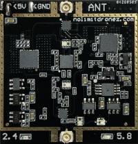
| Specifications | |||
|---|---|---|---|
| Model Number | Bidi2458mini-2.5W | Max RF Output Power | 2.5 W |
| Frequency Band | 2.4-2.5GHz,5-6GHz | Max RF Input power | 200mW |
| Cooling mode | Passive cooling | Min RF Input power | 10mW |
| Weight | <10 g | Optimum Input power | 100mW CE |
| PCB Size | 35*32*3.5 mm | Power Supply Voltage | 5 V |
| Output connector | IPEX 1 | Power Supply current | 1.2 A |
| input connector | IPEX 1 | Max Power dissipation | ≈ 6 W |
| 2.4GHz TX Gain | 13 dB | 5.8GHz TX Gain | 13 dB |
| 2.4GHz RX Gain | 13 dB | 5.8GHz RX Gain | 13 dB |
1.2 Stepdown Power Module
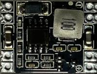
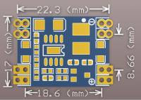
If your aircraft or remote has a 2S battery or higher, you will need to use a stepdown Power Module to reduce the voltage to 5 Volts, the required input voltage for the booster board. Our step-down module (Figure 2 and Figure 3) is suitable for 2S, 3S, 4S, 5S, or 6S power sources. You may have two of these modules supplied if the remote control for the aircraft listed on your order does not use a 1S power source. The board dimensions are shown in Figure 4.

| Specifications | |
|---|---|
| Dimensions (L x W x H): | 22 x 17 x 4mm |
| Input voltage: | 7-28V |
| Output voltage: | 5 V |
| Output current: | 1500 mA |
| Working temperature: | -45 ° to 85 ° C |
1.3 Step Up Power Module
If your aircraft or remote control uses a 1S power source, you will require a step-up power module to increase the voltage to 5 Volts, the required input voltage for the booster board. Our step-up power module (Figure 5 and Figure 6) accepts input between 1-5 volts, with a stable output of 5 volts. This module is suitable for a 1S power source only. We will not include this module if the remote control for the aircraft listed on your order does not use a 1S power source. The board dimensions are shown in Figure 7.
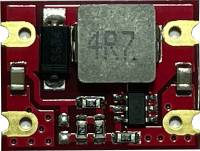

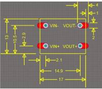
| Specifications | |
|---|---|
| Dimensions (L x W x H): | 17 x 13 x 5mm |
| Input voltage: | 1-5V |
| Output voltage: | 5 V |
| Output current: | 1500 mA |
| Working temperature: | -30 ° to 55 ° C |
| Protection class: | IP20 |
1.4 Remote Control Power Switch
Intelligent flight batteries in DJI equipment act as the master power switch for the aircraft and the booster board. The remote control is different because the battery is non-removable, and some of the power circuitry for the battery is on the circuit board for the remote control. Because of this difference, you have two options. You can either install a power switch (Figure 8), or a relay (Figure 9) . If you choose the power switch option, you need to drill or cut a hole in the enclosure for your remote control to allow you to activate the switch.

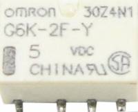
| Relay Specifications | |
|---|---|
| Dimensions (L x W x H): | 10 x 6.5 x 5.2mm |
| Coil Voltage (DC) | |
| Power Consumption | 100 mW |
| Switching Current | 1 A |
| Throw Configuration | DPDT |
| Working temperature: | -40 ° to 70 ° C |
| Protection class: | IP67 |
1.5 Antenna Connector Wires
The existing antenna lead will be disconnected from the RF board within your drone and your remote control and connected instead to the booster board. The connectors on the booster-board are all Ipex-1 connectors. The wires provided (Figure 11, 12, 13) will be selected based on the aircraft identified on your order.


1.6 Hookup Wire
If you did not order pre-assembly, we include hookup wire (Figure 14) to allow you to tap into suitable power sources. If you requested pre-assembly, we will solder some of these wires to your boards and leave a few extra ones in the package in case they're needed.

2. Tools
Before doing anything, you should check your kit has everything required from the list provided above. Make sure you have the correct antenna wires to match your aircraft. You will also need a few tools. A basic set would require:
- Screwdrivers suitable for your aircraft
- Pliers, cutters for stripping wires etc
- Soldering iron
- Solder
- Heat-resistant two-part epoxy glue for mounting the booster and power modules securely.
- Heatshrink to insulate your relay, step-up, and step-down boards.
- A basic multimeter is recommended but not mandatory.
3. Pre Assembly
We have soldered the hookup wire, booster boards, power modules, and the relay if you requested pre-assembly for your order. If you did not ask for pre-assembly, you need to do this before commencing the teardown of your equipment.
Note: You might prefer to do this later to optimise your cable routing inside the enclosure in some aircraft. Feel free to look ahead at community supplied videos for your equipment.
3.1. Connect power modules
The first part of the process is to connect the booster board to your power modules. The power modules we included in your kit depends on the aircraft identified when you placed your order. If your remote or aircraft has a 1S power source, this will require a step-up power module. If your remote control or drone has a 2S, 3S, 4S, 5S, or 6S battery, you need a step-down power module.
3.1.1 Step Up Power Module Connection
For use with a 1S power source, we will use a step-up power module (Figure 5) with the booster board (Figure 1). You will need to:
- Connect a Black wire between the Vo- pad on the power module to the GND pad on the booster board.
- Connect a Red wire between the Vo+ pad on the power module to the 5V pad on the booster board.
- Connect a Black wire to the Vi- pad on the power module.
- Connect a Red wire to the Vi+ pad on the power module.
3.1.2 Step Down Power Module Connection
For use with a 2S, 3S, 4S, 5S, or 6S power sources, we will use a step down power module (Figure 2) with the booster board (Figure 1). You will need to:
- Connect a Red wire between the Out+ pad on the power module to the 5V pad on the booster board
- Connect a Black wire between the Out- pad on the power module to the GND pad on the booster board
- Connect a Red wire to the In+ pad on the power module
- Connect a Black wire to the In- pad on the power module
3.2. Remote Control Power
Power in the aircraft is managed by turning off the power directly in the intelligent flight battery. There are two possible solutions to turn off the power to your booster board in the remote. Before we continue, identify which of the two booster boards and power modules that we prepared above you will use with your remote. If you've got a 1S power source in your remote, this will be the booster board connected to a red coloured step-up board.
Now that you have identified the correct module you will install in the remote; you need to decide if you wish to either
- Mount a hard-wired switch in your remote by cutting an opening and mounting the switch in the hole, or
- Use the supplied relay to control power to the booster board, which means you will not need to cut a hole in your remote.
3.2.1 Hard-wired switch option
If you are using a hard-wired switch (Figure 8), you will need to:
- Connect the free end of the Red wire on the power module to one of the pads on the switch.
- Connect a Red wire to the other pad on the switch.
3.2.2 Relay Switched Power
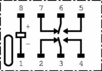
Instead of the switch above, you can use the relay (Figure 9) to control power for the booster board (Figure 1) in your remote. As you look at the diagrams below, take note of the orientation mark on the relay that matches the pinout diagram.
You will need to:
- Connect the free end of the red wire on the power module to pin 5 on the relay.
- Connect a Black wire to Pin 1 on the relay.
- Connect a Red wire to pin 8 on the relay.
- Connect a Red wire to pin 6 on the relay.
3.3 Insulate Relay and Power Modules
Before final installation in your equipment, you should use heatshrink to insulate the connections on the Relay, and on the power module. Review aircraft specific instructions for details of your wire routing before applying heatshrink.
4. Planning
Before you start a teardown of your equipment, it is essential to plan and make sure you have everything you need. Check that you have the tools mentioned previously. Also, check if you have answers to the following questions:
- Where will I tap into a power source on the aircraft?
- Where will I tap into a power source on the remote?
- If using a relay, where will I get relay voltage from inside the remote?
- Where will I mount the boards in the aircraft?
- Where will I mount the boards in the remote?
- What antenna connection do I need to tap into in the remote?
- What antenna connection do I need to tap into in the aircraft?
On our installation page below, we will be providing a table with links to aircraft-specific instructions. Before you do anything, ensure you answer all of these questions while reviewing the aircraft specific details. Or, if your equipment is not yet listed, consult the community on forums for further advice.
5. Install, test, and Reassemble
Now, it's time to install the board in your aircraft. If you have an available 5-volt power supply, you can use this to power the board and plug in the antenna leads to your equipment and test connectivity. As part of the process, there may be opportunities to test the operation of your booster board before making any physical changes to your aircraft.
The instructions below provide generic tasks required for installation. You should also review community supplied aircraft specific instructions before commencing installation in your equipment.
5.1 Aircraft Connection - Generic
Assuming you have completed pre-assembly, there are two tasks required. Connect the antenna signal wires, and connect power to the boards. Of course, you will need to teardown your aircraft to a state where you can access the power circuit and the antenna connection. Check our aircraft specific pages to see if there is a guide specific to your aircraft. If nothing is available, check youtube for teardown videos for your aircraft.
5.1.1 Aircraft Antenna Connection - Generic
Some aircraft have more than one antenna path. For example, the Phantom 4 Pro has one antenna for video signals and another for the C2 link (Command and control). But, we only have one booster board in our aircraft. Does that mean we will get a crap video feed and a tremendous C2 link? No. The good news is that DJI aircraft allows failover of the C2 connection to be embedded in the video feed if the reception is better. Once you have identified the antenna you intend to intercept; the task ahead is simple:
- Disconnect the chosen antenna connector from your aircraft mainboard, and connect it to the booster board to the socket marked ANT.
- NOTE: If your aircraft listed on your order does not use an IPEX1 connection, we have included an adaptor wire. One end of the adaptor cable will connect to the existing antenna lead in your drone, and the other end will connect to the IPEX1 connection on the booster board. TIP: Using heatshrink to shield the adaptor wire connection will help prevent a short to other items in your aircraft.
- Using the provided antenna link wire, connect one end to the other available IPEX1 socket on the booster board, and plug in the other end to your aircraft mainboard to the location where you disconnected the cable in the previous step.
5.1.2 Test Antenna Connection - Generic
As mentioned above, testing is important. Before you connect aircraft power to the booster power module, you could use a bench power supply as an input for testing purposes. Turn on both the aircraft and booster power modules, and verify the connection. However, depending on your aircraft you may not be able to use your flight battery while the aircraft is partially disassembled. Only proceed with this testing if you are able to power your aircraft before re-assembly. BUT:
- Please make sure your bench power supply meets the requirements of the power module before testing.
- Use commonsense. You should not have any props on your aircraft during testing for safety reasons.
- Do not turn on power unless your antenna wires are securely connected.
- During testing, isolate the components to prevent a short circuit to other components.
- Test quickly. The aircraft components and the booster board are designed to operate in the air. Without airflow, they may heat up and cause damage if left powered up for too long.
If your antenna signal path is connected correctly, you will be able to see your aircraft connection status on your remote control and/or connected display. However, you need to test from at least 30 meters away from the aircraft for this test to be valid. Even if your antenna wire is not connected correctly, you will still have localised signals radiated from the boards and leads. However, please return to power down the equipment as soon as possible after a successful test.
5.1.3 Aircraft Power Connection - Generic
The booster board requires power. As part of pre-assembly, we left a red and black wire connected to the power module. You need to connect these wires to a power source inside your aircraft. The connection point will differ from aircraft to aircraft, but in broad terms, it should be connected as close as possible to where the power from the flight battery comes into the circuit board in your aircraft. Before connection, use a multimeter to verify the voltage meets the input requirements for the power module in use.
5.1.4 Aircraft Board Mounting - Generic
It's time to mount the new booster circuit board inside your aircraft. We highly recommend using a two-part epoxy glue that is designed for thermal bonding. This will ensure that heat from the boards will be dissipated appropriately. One glue that would be appropriate is available via this link.
- Decide where to mount: Review other sections of our documentation to confirm if a recommended mounting location is suggested for your aircraft. If not, you should try to identify an area that will have enough room to allow airflow around the board while in flight.
- Glue it down: Follow the directions with your provided thermal epoxy glue for mounting.
- Insulate: Ensure all wires are insulated appropriately, and there is no risk of a short circuit during flight. Use heat-shrink if required - particularly if you are using an antenna adaptor.
- Secure the cables: Glue the cables in place if desired to prevent movement in flight.
5.1.5 Aircraft Reassembly and Testing
Now that the core work is done, you will need to reassemble your aircraft. There may be additional community supplied documentation specific to your model. If nothing is provided, do a search on youtube for teardown videos for your aircraft model for details on how to re-assemble. Finally, you should test. The best indication at this stage is that video signal quality - particularly at longer distances will be improved. However. Until the board in the remote is also installed, you may still observe issues. The remote control needs to acknowledge receipt of data packets from the drone. Until the booster is installed in the remote control, you will not get full range because any loss of those acknowledgement packets will cause retransmission.
5.2 Remote Control - Generic
Just like the aircraft, you have two tasks ahead. Connect the antenna signal wires and the power wires. If you decide to use the relay, you need to connect to two power sources: one for the relay coil and one to supply the power module.
Of course, you will need to teardown your remote control to a state where you can access the power circuit and the antenna connection. Check our aircraft specific pages to see if there is a guide for your equipment. If nothing is available, check youtube for teardown videos for your device.
5.2.1 Remote Antenna Connection - Generic
Like your aircraft, you need to identify the existing antenna connection. Use equipment specific documentation if available, or do some research before proceeding. The task ahead is simple:
- Disconnect the chosen antenna connector from your device mainboard, and connect it to the booster board to the socket marked ANT.
- NOTE: If your device does not use an IPEX1 connection, you need to use adaptor wires. One end of the adaptor cable will connect to the existing antenna lead in your device, and the other end will connect to the IPEX1 connection on the booster board. TIP: Using heatshrink to shield the adaptor wire connection will help prevent a short to other items in your aircraft.
- Using the provided antenna link wire, connect one end to the other available IPEX1 socket on the booster board, and plug in the other end to your aircraft mainboard to the location where you disconnected the cable in the previous step.
5.2.2 Test Remote Antenna Connection - Generic
Before you connect device power to the booster power module, you could use a bench power supply for testing purposes. However, this may not be possible depending on the state of your equipment. If you can still power up your device, turn on both your aircraft and the RC to verify the connection. Only proceed with this testing if you can power your remote before re-assembly. BUT:
- Please make sure your bench power supply meets the requirements of the power module before testing.
- Use commonsense. Do not have any props on your aircraft during testing for safety reasons.
- Do not turn on power unless your antenna wires are securely connected.
- During testing, isolate components to prevent a short circuit to other components.
The aircraft components and the booster board dissipate heat to the enclosure via the two-part thermal epoxy.* Test quickly. Powering the board for extended periods is not recommended.
- You should test from at least 30 meters away from the aircraft for this test to be valid. Even if your antenna wire is not connected correctly, you will still have localised signals radiated from the boards and leads.
If your antenna signal path is connected correctly, you will be able to see your aircraft connection status on your remote control and/or connected display. Please remember to power down the equipment as soon as possible after a successful test.
5.2.3 Remote Power Connection - Generic
The following steps will differ depending on your decision to use a switch or a relay.
5.2.3.1 Remote power connection - Switch - Generic
If you intend to use a switch, this will be simple. You have a red and black wire with a free end from the pre-installation build. Connect those wires to your battery source. Connect the red to the positive, and black to the negative. Please note: You are responsible for turning off the power switch when not in use to prevent battery drain.
5.2.3.2 Remote power connection - Relay - Generic
As part of pre-assembly, we have four wires ready to be connected.
Control power: The two wires from pin 1 and 8 on the relay need to connect to a power source that will only be active when the remote is powered up, such as a cooling fan. Check community supplied aircraft specific documentation for details of a suitable power source. If no details are available for your equipment, you can test using a multimeter to assist in locating an appropriate supply. This connection is only used to power the relay coil, drawing minimal current to power the ready.
Main power: The other two available red and black power wires need to connect to the main battery power supply. The intent here is to get as close as possible to the raw power coming from the battery cells.
- Connect the free end of the black wire from the power module to the negative terminal from your battery.
- Connect the free end of the red wire from pin 6 on the relay to the positive terminal from your battery.
SAFETY WARNING - ATTENTION!
![]()
Please take not of the following warnings:
- Turn off the power supply before removing or replacing the antenna. Powering the board without an antenna may cause damage to the booster board.
- The amplifier generates heat. Please be sure to provide sufficient heat dissipation. Make sure that the amplifier is in full contact with thermal conduction or cooled by a fan.
- Improper installation may cause damage to the amplifier or the host device!
- Please observe the local electromagnetic radiation regulations. Proper use of these amplifiers is your responsibility.