1. Connect power modules
The first part of the process is to connect the booster board to your power modules. The power modules we included in your kit depends on the aircraft identified when you placed your order. If your remote or aircraft has a 1S power source, this will require a step-up power module. If your remote or aircraft has a 2S, 3S, 4S, 5S, or 6S battery, you need a step-down power module.
1.1 Step Up Power Module Connection
For use with a 1S power source, you will need to:
- Connect a Black wire between the Vo- pad on the power module to the GND pad on the booster board.
- Connect a Red wire between the Vo+ pad on the power module to the 5V pad on the booster board.
- Connect a Black wire to the Vi- pad on the power module.
- Connect a Red wire to the Vi+ pad on the power module.
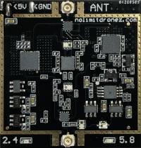
Booster Board
Step Up Board Power Module
1.2 Step Down Power Module Connection
- Connect a Red wire between the Out+ pad on the power module to the 5V pad on the booster board
- Connect a Black wire between the Out- pad on the power module to the GND pad on the booster board
- Connect a Red wire to the In+ pad on the power module
- Connect a Black wire to the In- pad on the power module
Booster Board
Stepdown Board Power Module
2. Remote Control Power
Switching is required for the power to the booster board in your remote. There are two possible solutions for connecting up your booster board in the remote. Before we continue, identify which of the two booster boards you will use with your remote. As described elsewhere, your remote may have a different power module. If you've got a 1S power source in your remote, this will be the booster board connected to a red coloured step-up board.
Now that you have identified the correct module you will install in the remote; you need to decide if you wish to either
- Mount a hard-wired switch in your remote by cutting an opening, or
- use the supplied relay to control power to the booster board, which means you will not need to cut a hole in your remote.
2.1 Hard-wired switch option
If you are using a hard-wired switch, you will need to:
- Connect the free end of the Red wire on the power module to one of the pads on the switch.
- Connect a Red wire to the other pad on the switch.
Manual Power Switch
2.2 Relay Switched Power
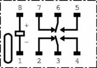
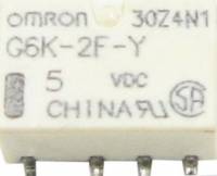
Instead of the switch above, you can use the relay to control power for the booster board in your remote. As you look at the diagrams below, take note of the orientation mark on the relay that matches the pinout diagram.
You will need to:
- Connect the free end of the red wire on the power module to pin 5 on the relay.
- Connect a Black wire to Pin 1 on the relay.
- Connect a Red wire to Pin 8 on the relay.
- Connect a Red wire to pin 6 on the relay.


